Why pressure drop is the whole story
In most buildings an intake louver is a minor component. In a data centre it is an energy decision. The reason is utilisation: cooling plant runs continuously at high load for the life of the facility, so any resistance in the air path is paid for every hour, forever.
That changes how the selection should be made. In a commercial building the usual instinct is to pick the smallest louver that passes the required airflow and meets a rain class. In a data centre the better instinct is to buy free area — to make the opening generous, keep face velocity low, and spend capital once rather than fan energy indefinitely.
The second-order effects all point the same way. Lower face velocity means:
- Less pressure drop, so less fan power for the same airflow.
- Better rain rejection, because water carry-over worsens as velocity rises.
- Less dust carry-over into filters, extending filter life and reducing their contribution to resistance.
- More margin when the facility is later run harder than designed, which data centres invariably are.
A generously sized intake is one of the few decisions in a data centre envelope that improves energy, reliability and maintenance simultaneously.
What the Test Data Has to Tell You
- ANSI/AMCA 500-L covers the laboratory methods for air performance (pressure drop), water penetration, air leakage and free-area measurement — the properties an intake selection depends on.
- The 2023 edition added a dedicated free-area measurement section, which is precisely the figure that fan calculations get wrong.
- A BS EN 13030 water-penetration class is tied to the face velocity at which it was measured, so rain performance and airflow cannot be selected independently.
Free area and face velocity, properly defined
Two numbers do most of the work, and both are commonly misused.
Effective free area is the open area the fan actually sees — after blade geometry, panel frame, structural mullions and any bird or insect mesh. It is not the blade free area quoted on a datasheet. Mesh in particular can remove a substantial share of the geometric open area, and on a data centre intake mesh is usually mandatory. The figure to design with is the installed effective area, measured per the methods in ANSI/AMCA 500-L, whose 2023 edition added a specific section on free-area measurement for exactly this reason.
Face velocity is airflow divided by the gross opening area. It is the parameter against which both pressure drop and water penetration are characterised, so it is the hinge of the whole selection. Pressure drop rises steeply — not linearly — with velocity, which is why modest increases in opening size buy disproportionate reductions in resistance.
The sequence that works:
- Start from the airflow each intake must pass, including any future-load allowance.
- Choose a target face velocity from the louver's tested curves, low enough that the water class holds and pressure drop is small.
- Derive the gross opening from airflow and that velocity.
- Check the effective free area after mesh and mullions, and iterate if it falls short.
- Carry the resulting pressure drop into the fan selection as a measured figure, not an allowance.
Our guide to performance louver selection works through the curves in more detail, and how to read a louver BOQ line item covers how to write the free-area basis so tenderers cannot read it two ways.
The filtration interface
An intake louver and the filter bank behind it are one system with one combined resistance, and they are usually specified by different people. Three consequences worth designing for.
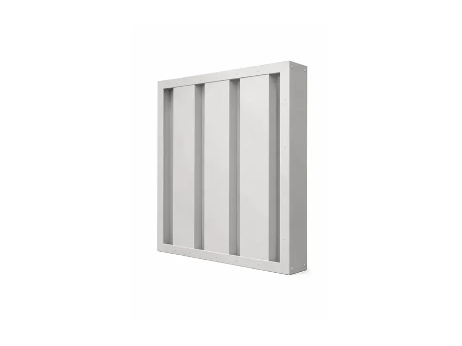
The louver protects the filters. Anything the louver rejects — rain, insects, leaves, heavy dust — is load the filters never see. A drainable louver that keeps bulk water out of the plenum prevents wet filter media, which is both a resistance problem and a hygiene one. On dusty sites a sand-trap louver removes the coarse fraction inertially before it reaches filtration, and the economics are straightforward: sand-trap pressure drop is constant, whereas filter pressure drop climbs as the filters load.
Combined resistance is what the fan sees. The fan has to be selected against the louver plus the filters at their dirty-condition resistance, not the clean figure. A design that is comfortable with clean filters and marginal with dirty ones will be operated with a cooling shortfall or filters changed too early.
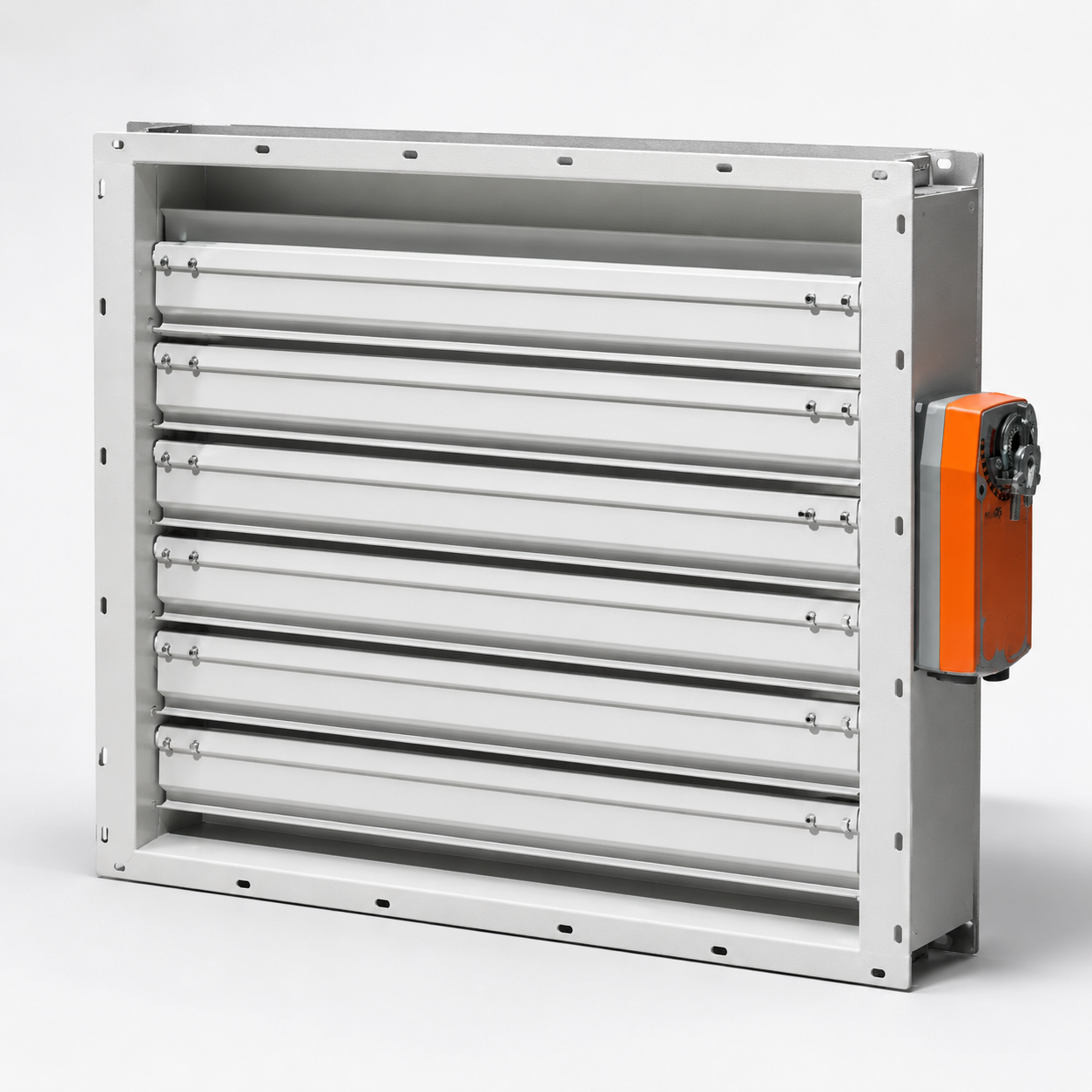
Free cooling makes the louver a control element. Where outside air is used directly, the intake is modulated, so the louver sits alongside control dampers whose leakage class matters when the intake is meant to be shut. That is a damper specification question — covered in low-leakage control dampers — and the two have to be coordinated as one assembly.
| Site condition | Intake selection | Why |
|---|---|---|
| Clean urban site | Drainable performance louver, low velocity | Minimises pressure drop, holds rain class |
| Dusty or arid site | Sand-trap louver ahead of filtration | Constant resistance, protects filter life |
| Heavy monsoon exposure | Drainable louver, lower velocity, drained plenum | Prevents carry-over onto filter media |
| Coastal site | Corrosion-resistant grade and coating | Salt attacks the louver before the filters |
| Direct free cooling | Louver plus low-leakage control damper | Intake must close tightly when unused |
Water, dust and redundancy
Three closing points that separate a data centre intake from an ordinary one.
Water in the plenum is a failure, not an inconvenience. A louver's rain class only describes what passes the blades; where that water goes is a detailing question. Drainable louvers need weep paths and a sill that discharges outward, and the plenum needs a drained floor. A drainable louver discharging into an undrained plenum has moved the water, not removed it.
Dust is cumulative and asymmetric. Filters catch dust and get more resistive; louvers catch dust and mostly do not. That makes inertial separation upstream a resistance-stabilising measure, which matters more in a facility whose cooling must stay predictable than in one where a filter change is routine. Our sand-trap louvers for data centres guide covers single versus double-stage selection.
Redundancy applies to the envelope too. Mechanical and electrical systems in a data centre are built with redundancy and maintainability in mind; intake paths deserve the same thought. An intake arrangement that cannot be isolated for cleaning or repair without reducing cooling capacity is a single point of failure dressed as a facade element. How that is formalised depends on the facility's own resilience framework, which is a project-level decision rather than something a louver standard addresses.
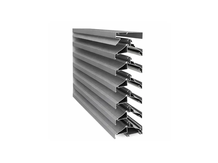
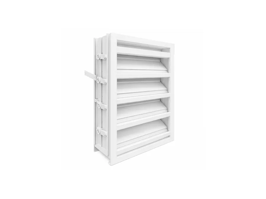
KBG Group manufactures drainable performance, sand-trap and acoustic louvers in extruded aluminium with air-performance and water-penetration data against AMCA 500-L methods, so intake pressure drop enters your fan calculation as a tested number. We will size intakes against your airflow, site dust and rain exposure and state the effective free area after mesh.
Frequently Asked Questions
What face velocity should a data centre intake louver be sized at?
Lower than a general-purpose intake. Pressure drop rises steeply with face velocity and water carry-over worsens at the same time, so an intake serving continuously running plant is normally sized well below the velocity at which the louver's rain class was demonstrated. The correct figure comes from the louver's own tested air-performance and water-penetration curves rather than from a rule of thumb.
How does intake louver pressure drop affect data centre energy use?
Directly and permanently. Fan power scales with the pressure the fan has to develop, so every pascal of avoidable loss at the intake is paid for continuously over the facility's life. Because data centre cooling runs year-round at high utilisation, a louver selected a class too small is one of the few design errors that keeps costing money every hour without ever announcing itself.
Should a data centre intake use a sand-trap louver?
Where the site is dusty, arid or exposed to construction or traffic dust, yes. A sand-trap louver is an inertial separator that forces the airstream to change direction so heavier particles drop out before reaching filters, which extends filter life and protects downstream equipment. On clean urban sites a drainable performance louver with properly specified filtration behind it is usually sufficient.
Who owns the free-area number — the louver supplier or the HVAC designer?
Both, which is why it has to be agreed explicitly. The louver supplier states effective free area measured per ANSI/AMCA 500-L after mesh and mullions; the HVAC designer uses that figure in the fan calculation. Problems arise when the designer uses a geometric blade free area and the supplier delivers a product whose installed effective area is materially lower.
Sizing intake louvers for a data centre hall or plant deck?
Our engineers review specifications and share test data at no cost. Typical response within one business day.